-40%
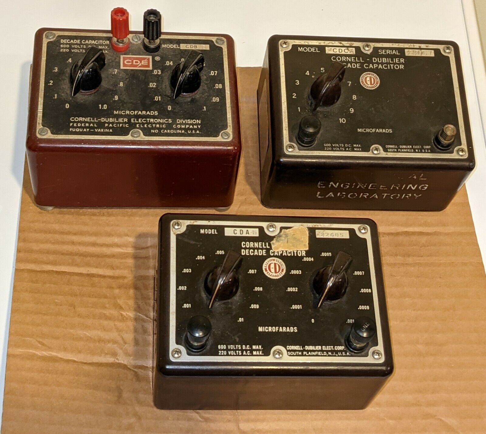
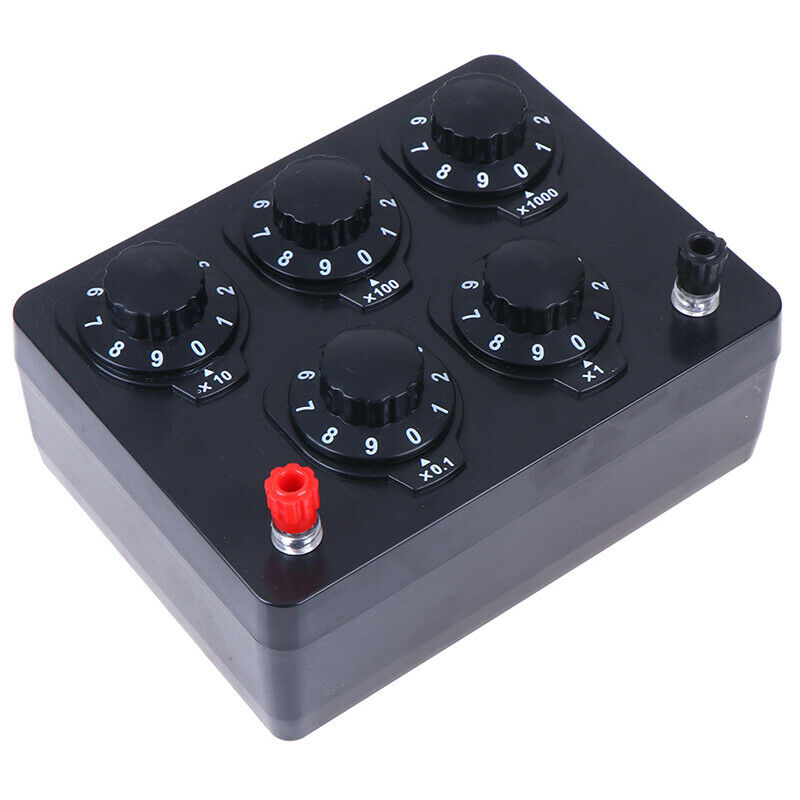
Cornell-Dubilier Capacitor Decade Boxes CDA5, CDB3, CDC5
$ 21.12
- Description
- Size Guide
Description
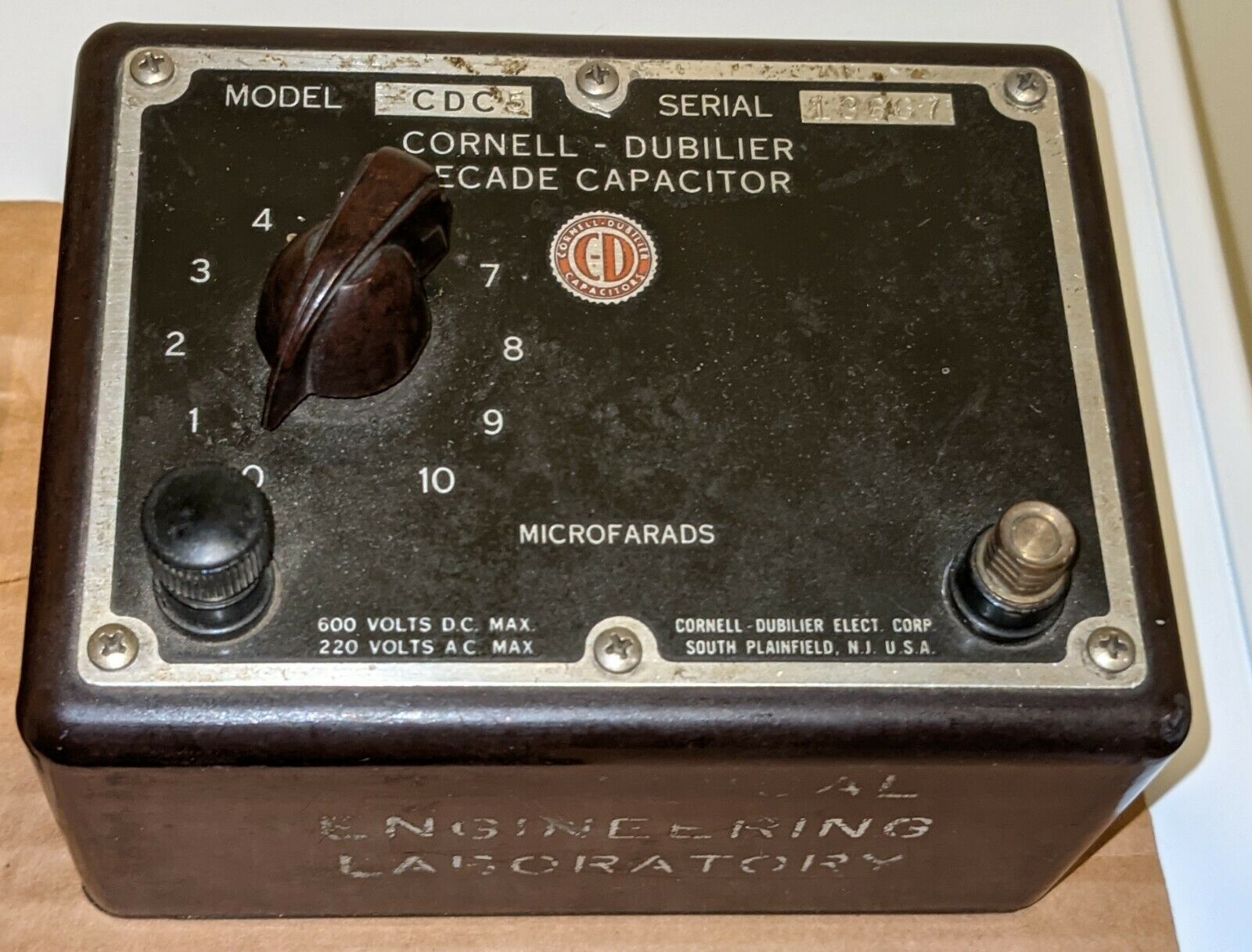
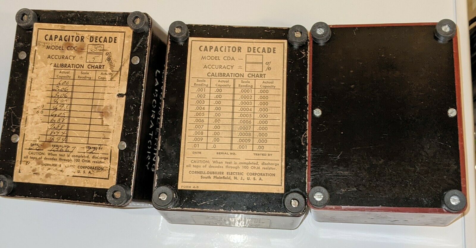
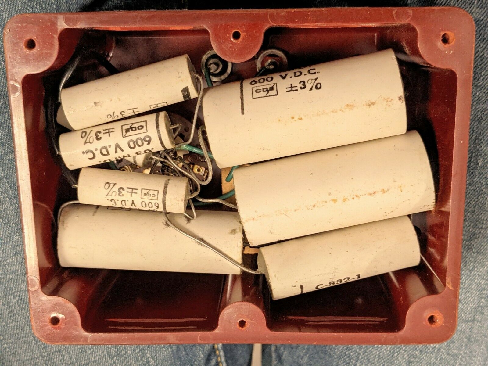
Cornell-Dubilier Capacitor Decade Boxes CDA5, CDB3, CDC5. The numerals were the tolerance (+/-5%,+/-3%, +/-5%) when they were new.One has a 1962 customer tag. Another has one from 1964. Two have aluminum bottom covers and the third appears to have a non-conductive cover.
One has a broken binding post knob...but the brass threaded collar still functions to make connection to wires.
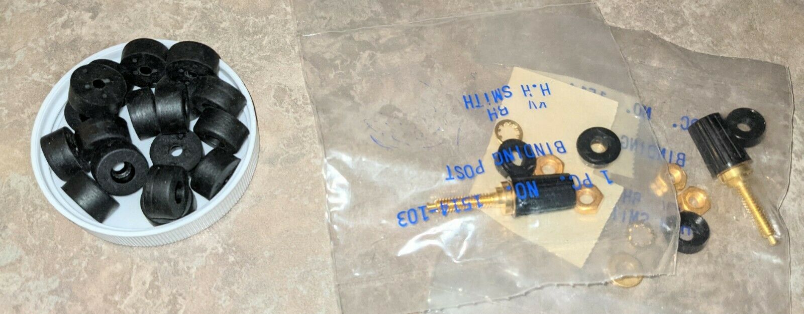
I replaced the decomposed or missing rubber feet on all three units.
The switches are good and values measured with a digital C-meter are stable.
All three are 600 VDC/220 VAC rated.
CDA5 'postage stamp' mica
974 pF 96.0 pF
2000 pF 196.1 pF
2970 pF 0.288 nF (range shift)
4110 pF 0.411 nF
5130 pF 0.503 nF
6.11 nF 0.604 nF
7.24 nF 0.718 nF
8.21 nF 0.811 nF
9.24 nF 0.911 nF
10.21 nF 1.003 nF
Total 11.21 nF
CDB3 - ceramic tube capacitors could be paper or fil. Previously-measured values were written on the bottom cover with black marker on the black cover...pretty close to same #'s, but no idea which meter was more accurate. Personally, I am never surprised to get different results from different handheld C-meters. Might be at a different test frequency or other reason.Impedance analyzer is better, but less common.
103.6 nF 11.42 nF
0.201 uF 21.4 nF
0.305 uF 32.8 nF
0.412 uF 42.0 nF
0.499 uF 52.4 nF
0.614 uF 63.5 nF
0.711 uF 73.0 nF
0.814 uF 84.4 nF
0.912 uF 94.4 nF
1.015 uF 105.8 nF
Total 1.121 uF
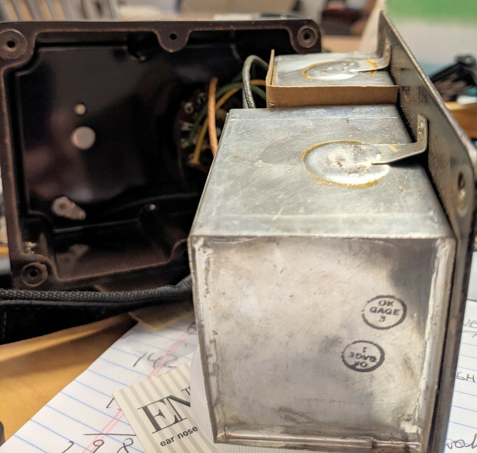
CDC5 These are the farthest from marked values. This makes me think these are paper dielectric...but the box is surprisingly heavy...maybe paper-in-oil. Remember, it's a decade box, not a lab standard. These capacitors are enclosed within two soldered metal boxes.
1.122 uF
2.30 uF
3.44 uF
4.39 uF
5.43 uF
6.70 uF
7.51 uF
8.65 uF
9.82 uF
10.94 uF
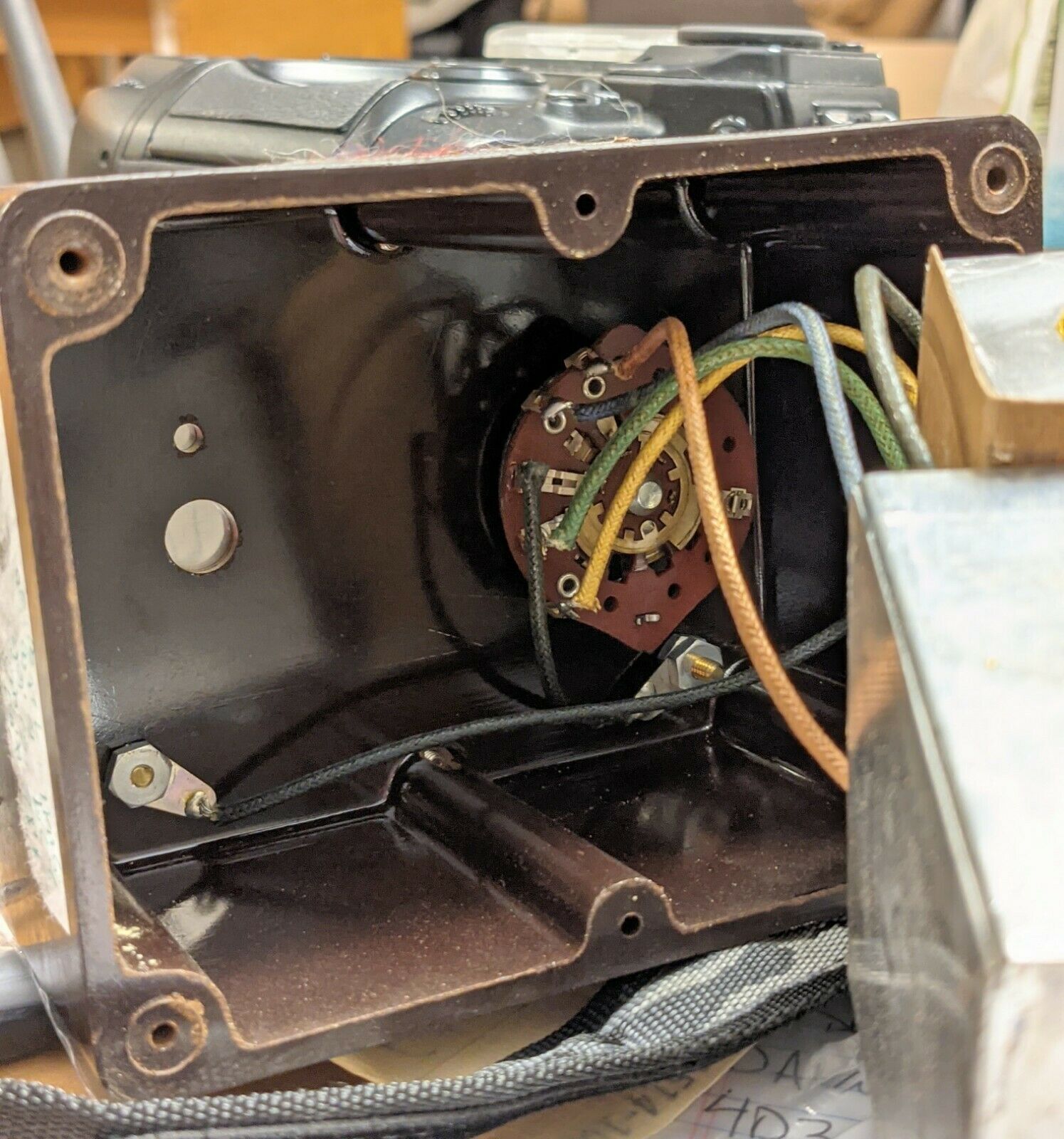
Edit: I installed new rubber feet on all three. I opened the CDC5 to look at the binding post accessibility, and remembered what the capacitor assemblies look like. The capacitors are enclosed in 2 soldered metal boxes that are riveted to the base. Wiring exiting the boxes extends into the case where the switch and binding posts are mounted. The binding posts should be easy to remove with a 5/16" nut driver/Spintite, but the studs are just long enough to pass thru the nuts. The wires are soldered to terminals. The 'candidate' binding post replacements, however, have 6-32 studs about 3/4" long. There could be a clearance problem requiring the studs to be shortened prior to installing. I'm leaving that to the new owner.
